


As application demands for large-scale concurrent reads and data distribution increase, such as in film and television rendering scenarios, traditional storage solutions like NAS often require significant investment in additional cache resources when the number of concurrent clients grows. To improve response times, data warm-up is also typically necessary. This not only incurs extra time overhead but also further increases resource strain.
JuiceFS, a distributed file system built on object storage, uses its high-performance architecture to aggregate throughput and reduce latency via distributed caching. It provides efficient support for large-scale concurrent client reads.
In this article, we’ll share a recent real-world test case, demonstrating how we successfully aggregated 1.45 TB/s of bandwidth using 4,000 application nodes and, in the process, ensured system stability by introducing a two-level cache pool configured with only two independent cache nodes.
Through this article, we aim to provide a practical solution for storage bottlenecks in high-concurrency, high-throughput scenarios and hope it sparks further discussion and exploration of storage optimization methods.
Traditional NAS: more nodes, slower storage
Our customer in this case was a film and television render farm user, where thousands of Windows nodes are launched simultaneously for daily rendering jobs.
- Application characteristics: Each node needs to read a batch of files (mostly reusable assets) to its local storage during rendering.
- Original pain points: When using the original public cloud NAS storage (mounted via SMB), increasing the number of nodes forced continuous addition of backend SMB service nodes to handle the surge in traffic and IOPS. This led to a steep rise in management complexity and cost. When concurrent nodes exceeded 1,000, the storage system often became overwhelmed.
- Critical requirement: An urgent need for a capability beyond the storage foundation to shoulder the pressure of application throughput.
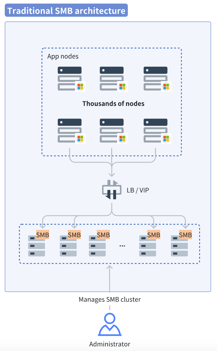
In the SMB service model, each client reads the full data volume from the SMB storage. This results in sustained high traffic at the server side. Administrators must continuously monitor the health of the SMB services. Once the load approaches maximum capacity, they need to promptly scale out, providing storage capability that matches the cluster size. This significantly increases operational pressure.
Utilizing idle resources: using numerous application nodes as distributed cache
JuiceFS released a new Windows client after Community Edition 1.3 and Enterprise Edition 5.2. It supports the mounting of the file system as a local drive via a .exe process, with usage similar to Linux.
However, in scenarios with massive numbers of clients, simply switching the application to the standard JuiceFS mount point -> distributed cache -> object storage chain could concentrate traffic on the independent cache layer. This potentially creates a new performance bottleneck. Instead of continuously scaling dedicated cache nodes, a shift in perspective is more effective: use the idle bandwidth and disk space of the vast number of application nodes, pooling them into a massive distributed cache pool.
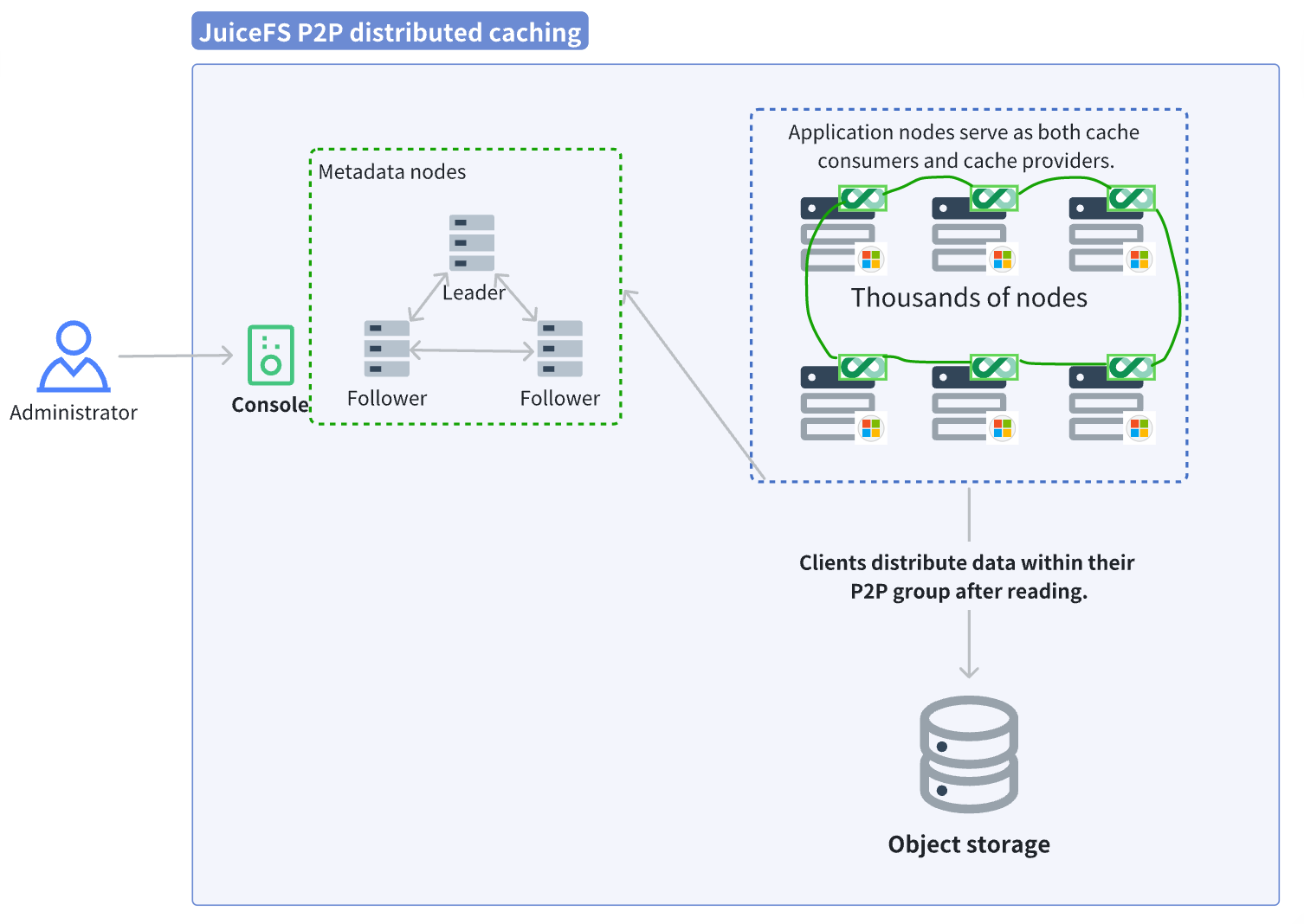
- JuiceFS distributed cache mode (P2P mode): A file only needs to be read once within the cluster; subsequent requests from other nodes fetch it directly from the neighboring nodes in the P2P cache pool.
- Object storage side: The back-to-source traffic is extremely low. After the initial cold read of a file, subsequent traffic is almost entirely handled by the cache pool.
- Resource requirements: No dedicated cache hardware is needed, only requiring each application node to contribute a portion of its disk and bandwidth.
In this solution, we did not configure a single independent cache node. All application nodes act as both consumers and providers (P2P mode).
Case study: 4,000 app nodes aggregate to 1.45 TB/s throughput
Test task: Each Windows node, without any warm-up (cold read), read 16 large files of 2 GB each. The total time for all nodes to finish reading was measured, observing the variance in time per node and checking for long-tail effects.
Configuration strategy: The 4,000 nodes were divided into multiple subgroups (500 nodes per group). The 16 data blocks of 2 GB each were distributed across nodes within a group using hashing to avoid all nodes simultaneously requesting data from the object storage. This would cause congestion.
The cold read process for the JuiceFS client:
- The Windows client read the 16 files of 2 GB each. Using a consistent hashing topology, it located the corresponding nodes for these data blocks within its 500-node cache group and sent requests to them.
- Upon receiving a data block request, the cache node found a local cache miss (cold read), so it fetched the data block from the object storage. After retrieval, it returned the data to the client and wrote it to its local cache for reuse by subsequent requests.
- Once the client had retrieved complete data blocks from all cache service nodes, the test ended. The time distribution (maximum, minimum) for all clients to finish reading was compiled to evaluate variance and long-tail situations.
The results for reading this batch of 16*2 GB files with different numbers of client nodes are as follows:
| Number of clients | Peak aggregated throughput | Total time (range/average) |
|---|---|---|
| 2,000 | 729 GB/s | 92s ~ 136s / Avg 107s |
| 2,500 | 921 GB/s | 87s ~ 109s / Avg 98s |
| 3,000 | 1.11 TB/s | 93s ~ 121s / Avg 106s |
| 3,500 | 1.34 TB/s | 89s ~ 112s / Avg 100s |
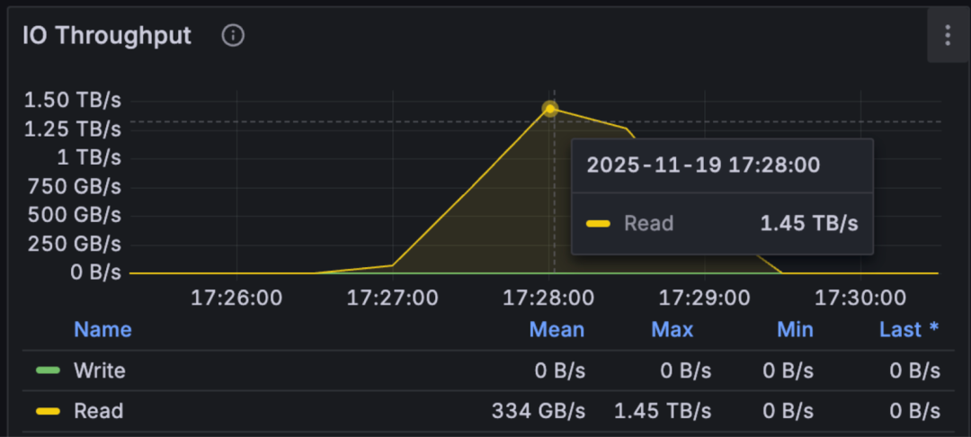
| 4,000 | 1.45 TB/s | 92s ~ 115s / Avg 101s |
The figure below shows aggregated throughput performance of JuiceFS with different client counts:
The results met expectations in all aspects:
- Stability: Whether with 2,000 or 4,000 nodes, the total time to read the data remained stable at around 100 seconds.
- Scalability: The 4,000 nodes successfully aggregated an ultra-high bandwidth of 1.45 TB/s. Theoretically, within the limits of metadata capacity, this architecture can achieve continuous horizontal scaling, potentially supporting cache node clusters at the scale of tens of thousands.
Reference mount parameters for application nodes:
juicefs.exe mount juice-fs X: --cache-group=primary --buffer-size=4096 --enable-kernel-cache --as-root --subgroups=8
Thus, without using a single independent cache service node, we aggregated 1.45 TB/s of read capability using the customer’s application nodes. By offloading the vast majority of traffic from the object storage to this distributed cache layer formed by client nodes, we alleviated the burden on the underlying storage at zero additional hardware cost.
In actual application scenarios, such extremely high throughput might not always be achievable, as cache efficiency is often related to data duplication. In practice, the files read by each node are not entirely the same. Nonetheless, this solution is an effective method for storage scaling. Even a partial improvement can yield significant benefits with almost no additional cost.
Enhanced stability: two-level distributed caching
While the caching effect was impressive, the customer expressed concerns about system stability. For example, in some scenarios, application nodes might be destroyed immediately after completing their tasks, and these application nodes also served as cache nodes. When a large number of application nodes went offline suddenly, the cache stored on these nodes was also lost. This could cause a massive surge of traffic to fall back to the object storage, turning it into a bottleneck and affecting overall stability. To address caching performance issues caused by application node volatility, we proposed a two-level distributed caching solution, as shown in the architecture diagram below:
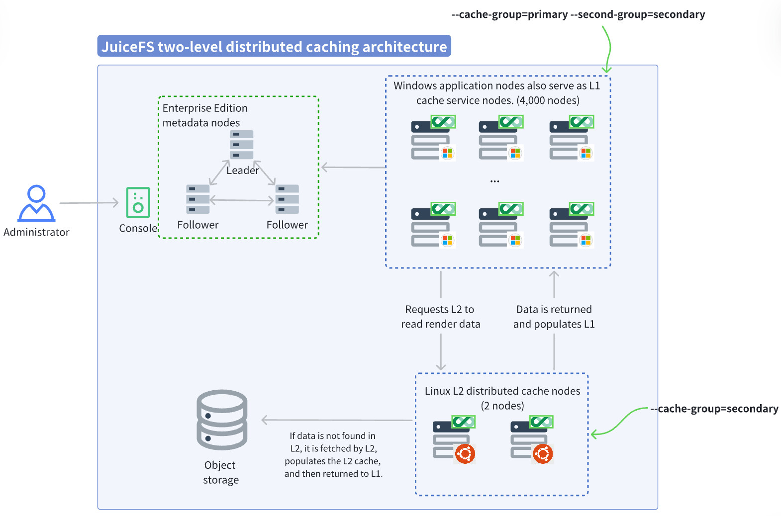
The second-level (L2) cache pool sits between the first-level (L1) cache pool and the object storage. On an L1 cache miss, data is first attempted to be retrieved from L2. If it's also a miss in L2, it falls back to the object storage. This effectively mitigates the impact of L1 cache node churn. Since L2 only handles the fallback traffic from L1 misses (including cold reads and warm-up), its capacity and performance planning only need to cover the available throughput of the object storage side. In this test, configuring just two independent cache nodes as L2 was sufficient to meet the demand.
With the addition of the L2 cache pool, the read process changes as follows:
- The Windows client reads the 16 files of 2 GB each. It determines the specific node for the data block within its L1 cache group via the consistent hashing topology and simultaneously requests data from the L2 cache group.
- Due to a cold read, there is no data in the L2 cache group. The L2 cache node fetches it from the object storage and fills the L2 cache pool.
- The data block is returned from the L2 cache pool to the L1 cache pool for population, and then distributed P2P within the L1 cache pool.
- At this point, most traffic is concentrated within the L1 cache pool. L2 only handles the minimal traffic falling back to object storage. Therefore, even with only a few L2 nodes, they do not become a performance bottleneck. The role of the L2 cache pool is to act as a low-latency local substitute for the object storage.
Even if a large number of L1 application nodes go offline, causing the cache topology to change and requiring data blocks to be re-downloaded. Data can still be fetched from the nearby L2 cache pool. As long as the proportion of nodes going offline is controlled reasonably, application operations are barely affected.
L2 cache group mount parameters:
juicefs mount juice-fs /jfs-cache --cache-group=secondary --cache-size=-1 --cache-dir=/data* --free-space-ratio=0.01 --buffer-size=10240 --max-downloads=400
L1 (application node) mount parameters:
juicefs.exe mount juice-fs X: --cache-group=primary --second-group=secondary --buffer-size=4096 --enable-kernel-cache --as-root --subgroups=8
Furthermore, the two-level distributed caching is highly suitable for scenarios requiring the reuse of existing cache pools.
For example, consider a batch of cache-pool applications located in Seattle, with a total capacity of 2 PiB, named cache-group-st. Suddenly, applications in Chicago also need to use the same data, which is almost the same as the Seattle data.
Instead of warming up the 2 PiB of data from Seattle’s object storage, we can configure the Chicago cache group with --second-group=cache-group-st. When Chicago application requests data, it prioritizes reading from the Seattle cache pool over a dedicated line, achieving very fast and stable speeds (within 2 ms latency). This eliminates the complex process of repeated data warm-up, allowing the Chicago applications to launch directly. This is extremely convenient.
Summary
Through this extreme stress test with 4,000 nodes, we successfully transformed the large-scale idle resources of a compute cluster into a storage pool with up to 1.45 TB/s of throughput. The introduction of a secondary cache effectively addressed "last-mile" stability concerns. By employing JuiceFS' storage software architecture, the potential of client clusters can be fully unlocked, achieving significant performance improvements without increasing additional hardware costs.
This solution is applicable to scenarios such as:
-
High-concurrency repeated read scenarios: Such as model training/inference data fetching, container image distribution, and film and television rendering. The more nodes, the greater the P2P cache benefit.
-
Elastic computing scenarios: Where application nodes frequently scale in and out on a large scale (such as spot instances). Using a two-level cache architecture ensures continuity and stability of data access.
-
Hybrid cloud / multi-cloud architectures: Leveraging the secondary caching mechanism allows for the reuse of cache pool resources across different regions, minimizing object storage calls and transfer costs associated with repeated warm-up.
If you have any questions for this article, feel free to join JuiceFS discussions on GitHub and community on Slack.